Creative coding: designing my logo using code
I've been learning to code and make generative art using Processing and GLSL (shaders) this past week. My fascination with creative coding started back in third grade, when I first learned how to make simple art in computer class using LOGO/BASIC. Now I’ve returned to it, thanks to The Coding Train on YouTube. It's really fun, and I like his teaching style.
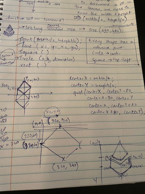
After following a few Coding Train videos, one of my first goals was to design my logo using only the default 2D primitive shapes from the Processing reference documentation. The main objective was to understand the coordinate system, and I thought this would be a good opportunity / challenge to understand the fundamentals of creative coding.
So I spent the entire day working with Cartesian plane coordinates, going back and forth between plotting on paper and validating my work on screen. Ultimately, I was able to successfully draw my logo using just the shapes provided by Processing.

One of the first steps, after setting the window size, was using a quad() to build the diamond shape from the upper half of my logo. This was a bit tedious because I was confused by how Cartesian coordinates work in the context of the output window. By default, the origin is positioned at the top-left corner, with the X-axis running horizontally and the Y-axis vertically. Also, unlike typical Cartesian planes, there are no negative coordinates.
The real challenge came next. After spending half the day figuring out coordinates for the diamond shape, working out the 'V' shape for the second part of my logo was a bit more difficult. Fortunately, Processing provides a function called beginShape(), to build custom shapes. I approached this by first plotting out points in my notebook, then transferring the coordinates to my Processing program and using the point() function to map them out on screen. This step took a LONG time, and I made heaps of errors while calculating the points; still getting used to the cartesian plane!
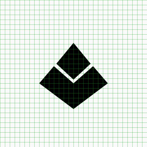
After blocking out the shape, I used all the points in consecutive vertex() functions to generate the bottom half of my logo. This is how it looked as a whole—woot! I also cleaned up the code and defined center points X and Y using half of the window's width and height respectively to align both shapes and achieve a symmetric look.
    float centerX = width / 2;
    float centerY = height / 2;

    quad(centerX, centerY - 85,  // Top vertex
        centerX - 70, centerY,   // Left vertex
        centerX, centerY + 65,   // Bottom vertex
        centerX + 70, centerY);  // Right vertex

    beginShape();
    vertex(centerX - 80, centerY + 10);
    vertex(centerX - 145, centerY + 80);
    vertex(centerX, centerY + 185);
    vertex(centerX + 145, centerY + 80);
    vertex(centerX + 80, centerY + 10);
    vertex(centerX, centerY + 80);
    endShape(CLOSE);

However, I noticed the shape wasn't centered with respect to the window/canvas. To fix this, I defined an offset value and applied it to both shape functions to center the entire logo within the window.
To test for symmetry, I defined a function that draws a grid on screen.
void drawGrid() {
    noFill();
    stroke(0, 175, 0, 150);

    for (int x = 0; x <= width; x += 20) {
        line(x, 0, x, height);  // Vertical lines
    }

    for (int y = 0; y <= height; y += 20) {
        line(0, y, width, y);   // Horizontal lines
    }
}

This was the end result! For the next steps, I want to learn how to apply rounding to all the vertices of my logo to achieve a smoother, refined look. (Bonus points if it matches with my original logo design!)
